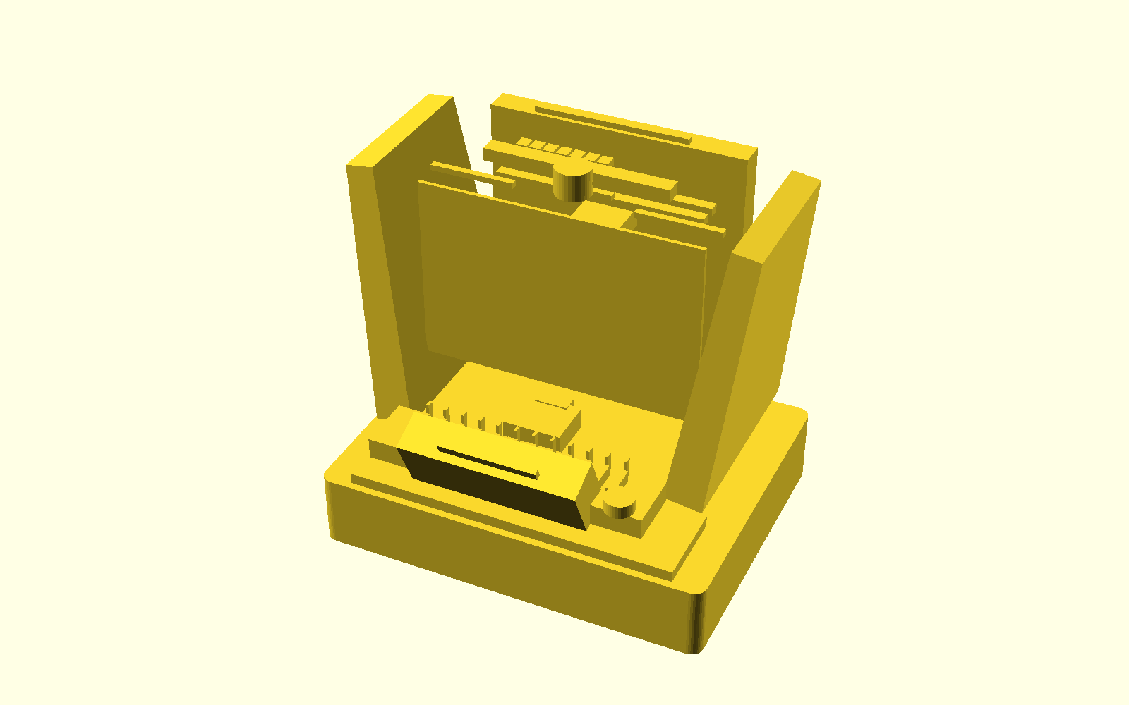
Manually indexed 12-slot wire tray, slack combs, and a dowel-located connector cartridge stay accessible at the front.
LF-P1-R02 / DEVELOPMENT DESIGN
Visible precision for small-batch harness assembly.
A proposed supervised workstation for guided insertion of pre-crimped terminals, connection mapping, and traceable engineering records.
SELECTED CONFIGURATION
A compact workcell built around the actual insertion path.
Clear guarded chamber exposes the X/Y/Z insertion head, force mount, camera, and task lighting without turning the machine into a generic enclosure.
Graphite spine carries rails, cable chain, lighting, and service routing; warm light-gray folded supports form the load path.
SUPERVISED WIRE CYCLE
Presentation is manual. Motion is bounded. Results remain traceable.
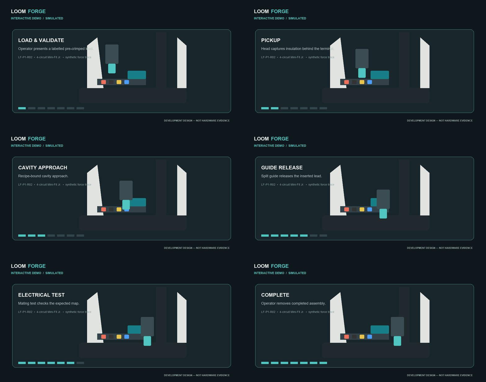
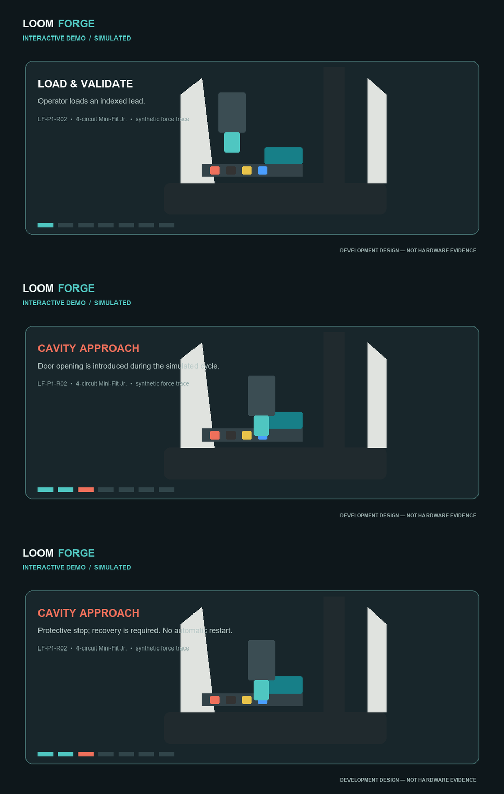
- 01 Open the interlocked guard; place labelled pre-crimped lead terminal-forward in its indexed slot.
- 02 Route slack through passive combs and close the guard. Recipe, fixture, and calibration are validated.
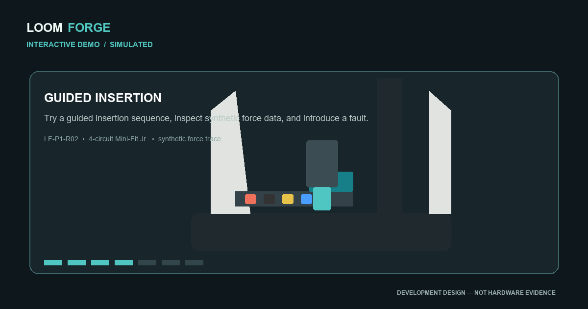
- 03 The compact head grips insulation, captures the terminal in a keyed guide, and approaches the selected cavity.
- 04 Controlled insertion monitors force and travel. A split guide opens for release; no blind retry is used.
- 05 Mating/far-end test checks connection mapping; operator removes the assembly after the guarded cycle.
FUNCTIONAL LIGHTING
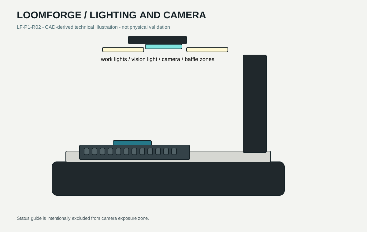
Illumination has three jobs.
Diffuse neutral-white work light supports loading. A separately baffled vision zone is reserved for inspection. A restrained status guide is paired with text and physical indicators; lighting is not a safety system.
ENGINEERING PACKAGE
Designed for review, fabrication planning, and manufacturer-led validation.
Included now
- Parametric OpenSCAD source and generated STL
- Mechanical part register and preliminary BOM
- Simulation, recipes, reports, and state/fault tests
- Research, safety, manufacturing, and validation documentation
Shareable media kit
WHAT REMAINS UNVERIFIED
Conceptual geometry and synthetic data are not hardware evidence.
Critical blockers include controlled connector dimensions, guide geometry trials, tolerance stack release, purchased motion/safety hardware selection, electrical release, and a manufacturer-led safety and validation program.
Read unresolved items